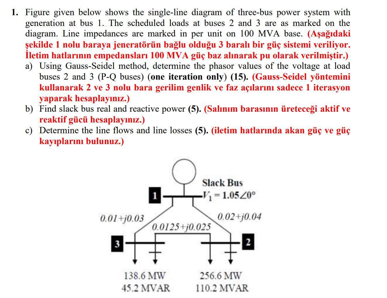
1. Figure given below shows the single-line diagram of three-bus power system with generation at bus 1. The scheduled loads at buses 2 and 3 are as marked on the diagram. Line impedances are marked in per unit on 100 MVA base. (Aşağıdaki şekilde 1 nolu baraya jeneratörün bağlu olduğu 3 baralı bir güç sistemi veriliyor. İletim hatlarının empedansları 100 MVA güç baz alınarak pu olarak verilmiştir.) a) Using Gauss-Seidel method, determine the phasor values of the voltage at load buses 2 and 3 (P-Q buses) (one iteration only) (15). (Gauss-Seidel yöntemini kullanarak 2 ve 3 nolu bara gerilim genlik ve faz açılarını sadece 1 iterasyon yaparak hesaplayınız.) b) Find slack bus real and reactive power (5). (Salınım barasının üreteceği aktif ve reaktif gücü hesaplayınız.) c) Determine the line flows and line losses (5). (iletim hatlarında akan güç ve güç kayıplarını bulunuz.) Slack Bus Vi= 1.05 20° 0.01+0.03 0.02+j0.04 0.0125 +0.025 3 138.6 MW 45.2 MVAR 256.6 MW 110.2 MVAR
没有找到相关结果