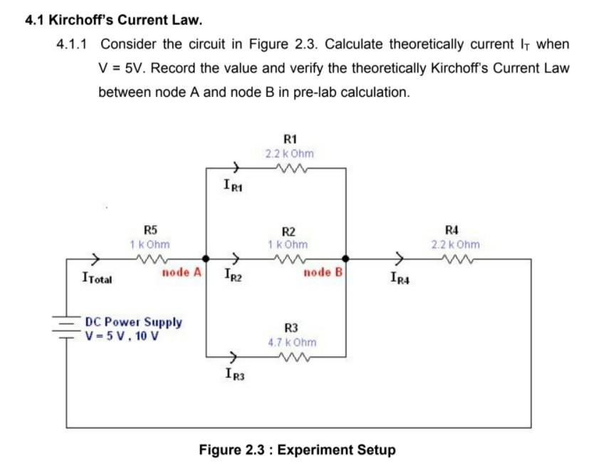
4.1 Kirchoff's Current Law. 4.1.1 Consider the circuit in Figure 2.3. Calculate theoretically current It when V = 5V. Record the value and verify the theoretically Kirchoff's Current Law between node A and node B in pre-lab calculation. R1 2.2k Ohm → IR1 R5 1 kOhm R2 1 k Ohm R4 2.2k Ohm I Total node A IR2 → IR4 node B DC Power Supply V-5V, 10 V R3 4.7 kOhm IR3 Figure 2.3: Experiment Setup
PRE LAB CALCULATIONS. V = 5 V. 5.1 Kirchoff's Current Law at node A. 5.2 Kirchoff's Current Law at node B.
5.3 Kirchoff's Voltage Law for loop V,R5, R1, R4. 5.4 Kirchoff's Voltage Law for loop V,R5, R2,R4. 5.5 Kirchoff's Voltage Law for loop V,RS, R3, R.
Table 2.1 DC Voltage Power Supply (V) Current V=5V V=10V ITotal(mA) IR1(mA) IR2(mA) IR3(mA) IR4(mA) Table 2.2 DC Voltage Power Supply (V) Voltage Drop V=5V V=10V Calculation Experiment Experiment VR1(V) VR2(V) VR3(V) VR4(V) VRS(V)
6.1 Write down current relationship for junction a, b and c of the network shown in figure below and determines the currents 13, 14 and 15. 11 - 3A 12 - 1A 13 15 16 = 1A b Junction a; Junction b; Junction c; A A А. 7. DISCUSSION: 8. CONCLUSION: Page 8 / 8
没有找到相关结果