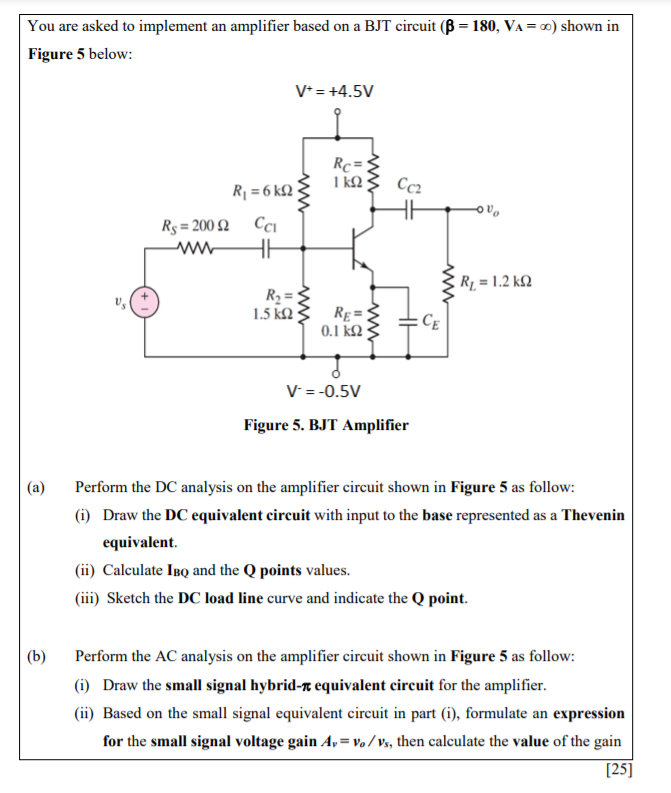
You are asked to implement an amplifier based on a BJT circuit (B = 180, VA= ) shown in Figure 5 below: V+ = +4.5V Rc 1 k2 : WW Cc2 R = 6k92 Rs = 2002 CCI HE R2 = 1.2 k22 www R2 = 1.5 k 2 ww Re= 0.1 k 23 CE V = -0.5V Figure 5. BJT Amplifier Perform the DC analysis on the amplifier circuit shown in Figure 5 as follow: (i) Draw the DC equivalent circuit with input to the base represented as a Thevenin equivalent. (ii) Calculate Ibo and the Q points values. (iii) Sketch the DC load line curve and indicate the Q point. (b) Perform the AC analysis on the amplifier circuit shown in Figure 5 as follow: (i) Draw the small signal hybrid-r equivalent circuit for the amplifier. (ii) Based on the small signal equivalent circuit in part (1), formulate an expression for the small signal voltage gain A,= ve/vs, then calculate the value of the gain [25]
没有找到相关结果