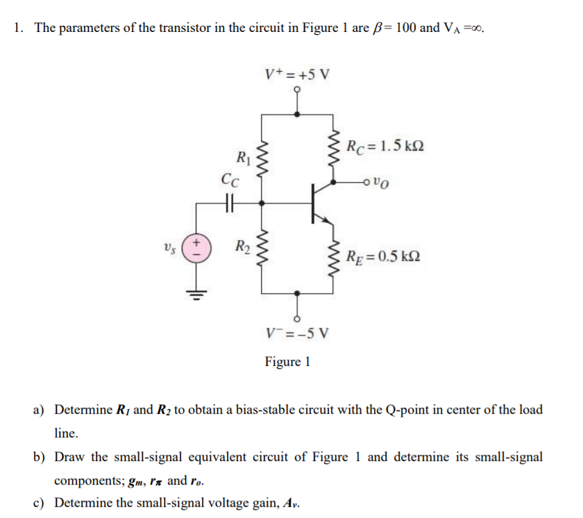
1. The parameters of the transistor in the circuit in Figure 1 are B= 100 and Va=. V+ = +5 V Rc=1.5k 2 Ri CC OVO HE Us R2 RE=0.5 k 2 V-=-5 V Figure 1 a) Determine R, and R2 to obtain a bias-stable circuit with the Q-point in center of the load line. b) Draw the small-signal equivalent circuit of Figure 1 and determine its small-signal components; gm, rr and ro. c) Determine the small-signal voltage gain, Ay.
没有找到相关结果