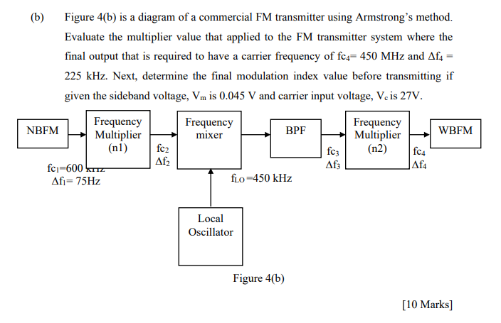
(6) Figure 4(b) is a diagram of a commercial FM transmitter using Armstrong's method. Evaluate the multiplier value that applied to the FM transmitter system where the final output that is required to have a carrier frequency of fc = 450 MHz and Aft = 225 kHz. Next, determine the final modulation index value before transmitting if given the sideband voltage, Vm is 0.045 V and carrier input voltage, Veis 27V. Frequency Frequency Frequency NBFM Multiplier mixer BPF Multiplier WBFM (nl) fc2 fcz (n2) fc4 fci-600 kr Afz Aft Af= 75Hz fuo=450 kHz Af2 Local Oscillator Figure 4(b) [10 Marks]
没有找到相关结果